


Product Description
The device is used for wiring tests so it can simulate the correct signal and compare it to the scan tool. Allows you to eliminate the need to replace sensors and diagnosing the correct fault.1. Simulated Resistance
2. Simulated Voltage from 0.2 to 7V in 0.1 increments
3. Simulated Sine Wave
4. Simulated Square Wave
5. Simulated Temperature Coefficient Sensors:
6. Simulated Throttle & Pedal Sensor sequences
7. Oxygen Sensor: Testing Mode and Simulated mode
You can simulate most sensors, injectors or actuator as ABS sensor, lambda sensor, EGR sensor, CKP sensor, knock sensor, map sensor etc.
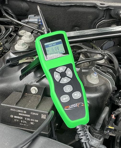
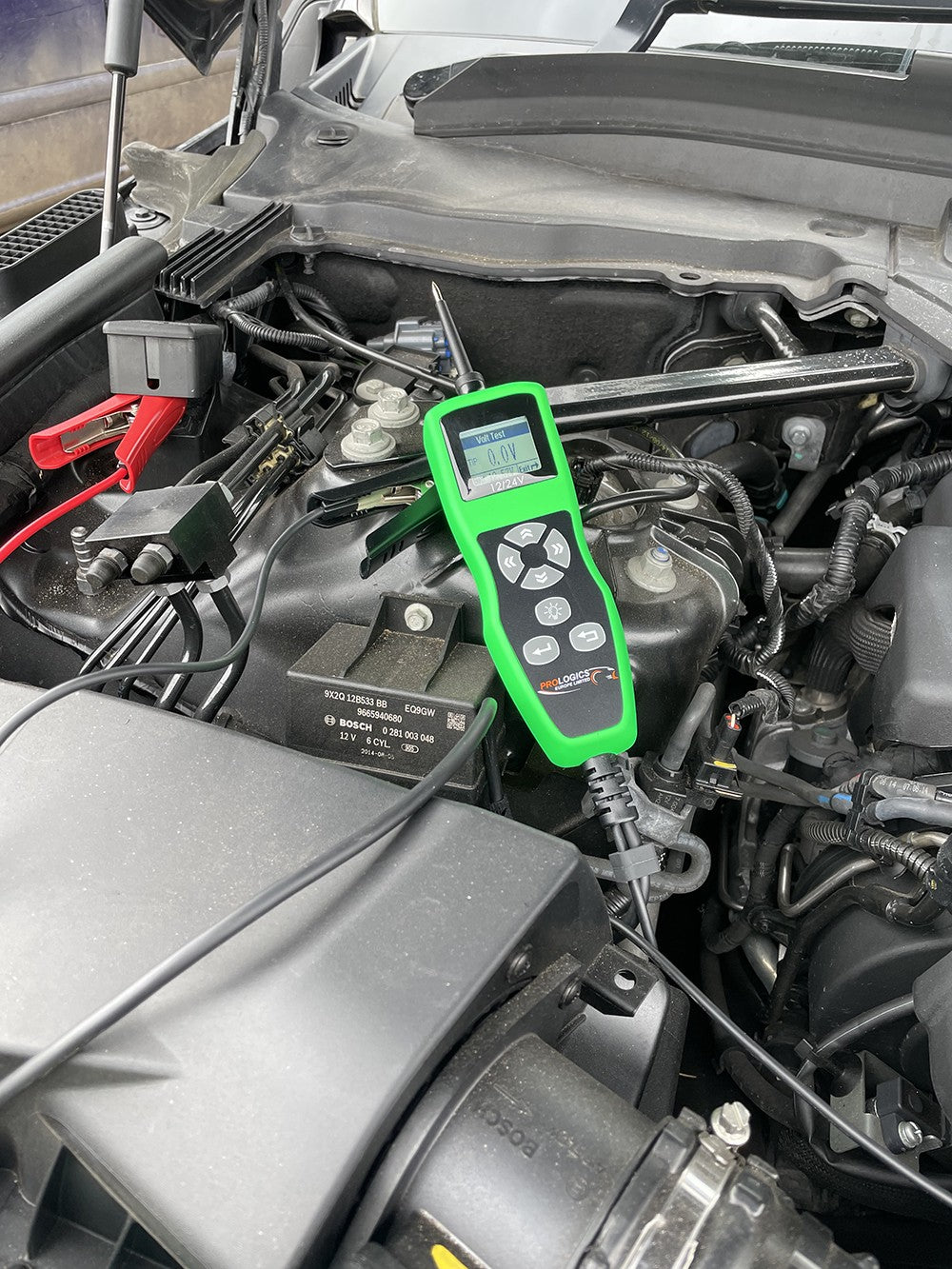
This Probe is mainly used for simulation of the signals generated by different types of sensors in the vehicle. It can be used in all automobiles (12V/24V systems) with ECM / ECU either independently, or very often it is used together with a diagnostic scanner to distinguish faults whether that lies in the sensor itself or related to the connection (connector or wires) during troubleshooting phase. From the reading of Error codes on the diagnostic scanner, faults are recognized, as the sensors data which is imitated at the same time by this probe were observed. Through the simulation of the sensor output signals, the ECM / ECU response as well as its efficiency can be estimated.
Typical Applications
1. Simulates vehicle sensors output signals of Crankshaft Position (CKP) sensor, Camshaft Position (CMP) sensor, ABS sensor, Wheel Speed (WSS) sensor, Coolant Temperature sensor, Lambda (O2) sensor, MAF, MAP, etc.
2. Imitates sensor’s signals at different working modes of the engine. This is done by simulating the signals with this VR2 Probe without removing the sensor unit. During simulation process, the ECU’s activities are monitored on the Live Data screen displayed by the Diagnostic Scanner. In this way, we can determine the real cause of the fault whether it lies in the cables connected to the ECU or at the sensor itself before any replacement of parts take place.
3. Simulates sensor signals of: Resistance type: 100Ω ~ 20KΩ output
Voltage type: 0.1V ~ 7.0.0V DC at 150 mA output,
0.1V ~ 7.0V DC at maximum 3.0 Amp power feed
Frequency modulated type:
Sine wave: 1Hz ~ 10,000Hz fixed at 5V, 150mA output.
Square wave: 1Hz ~ 20,000Hz (adjustable 0.1V to 12.0V at 150mA output).
4. Simulates Duty Cycle (%) from 1% to 100% signals with adjustable voltage from 0 to 12V Positive (+) or Negative (-) supply at 150mA output.